i’ve spend the last two weeks house-sitting at my parents place while they are on holiday. this has given me time to deep dive into some larger topics i have been meaning to get around to.
one of these topics was the design and fabrication of panels for underscores circuits (having unlimited access to a laser cutter over this time helped!). i made a half vlog / half tutorial style video to document this exploration – you can see on videos.scanlines or on youtube:
types of panels
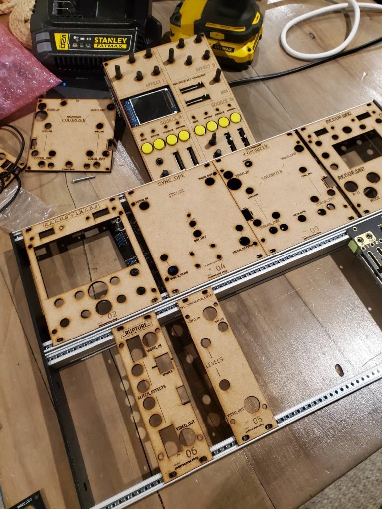
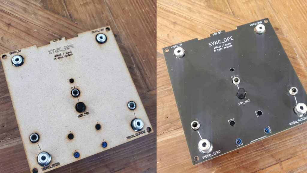
sometimes i get asked if there are enclosures/front-panels available for the pcbs i sell (there actually have been a few community contributed designs for the recurboy and i_n_c_u_r circuits) but so far nothing from me. this will change soon with the addition of two enclosure options – stand-alone sandwich and eurorack front-panel for the following circuits:
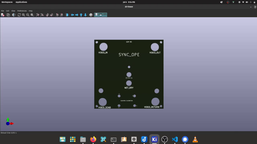
- sync_ope
- recurboy
- _rupture_
- two_comparator_effect
- i_n_c_u_r
originally i planned to prototype with laser-cut MDF (and share these files so others can laser-cut also) but only stock the FR-4 versions in the shop (since these would be cheaper and tend to look quite professional) – however after seeing the MDF i think i prefer them to FR-4.. i wonder if there would be any interest in stocking MDF (or even bamboo) lasercut panels too ?
euro-friendly designs
although definitely not eurorack modules themselves a number of these underscores circuits were designed to be euro-friendly, in the sense that you could mount them in eurorack case with the appropriate front-panel if you wanted to.
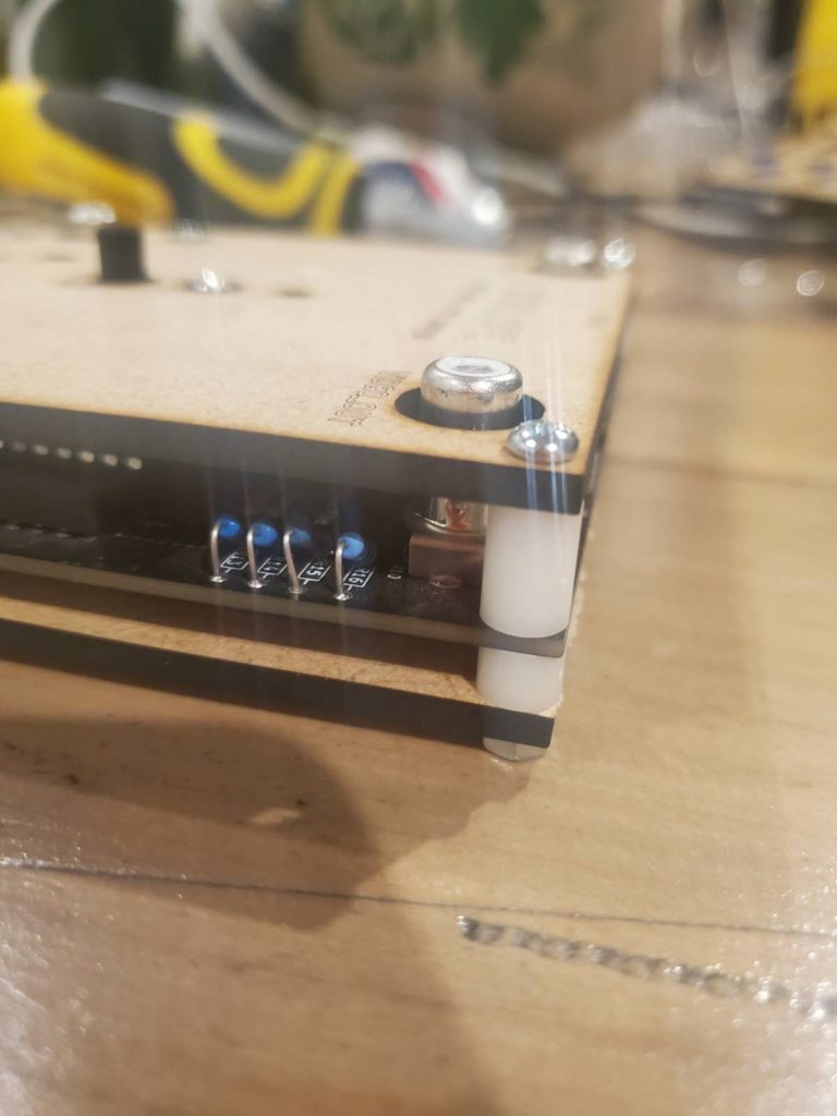
all the interfacing parts of these circuits are vertically mounted and the pcbs are at most 100mm tall. all circuits run on single-rail power (mostly 5v) but some have footprints for euro-power headers anyway and the others you could mount a vertical barrel-plug on the bottom of the pcb allowing a small eurorack-to-barrel-jack converter to sit inside your case and power from beneath:
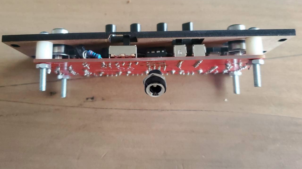
as i mentioned in the video there are a few other things to consider when adapting to eurorack – the small slide switches i usually use sit a bit too low for comfortable switching (i would love to try 3d-print some switch-caps for these when i get a printer!) and i would recommend choosing longer shafts on the pots than the ones usually supplied with my kits…
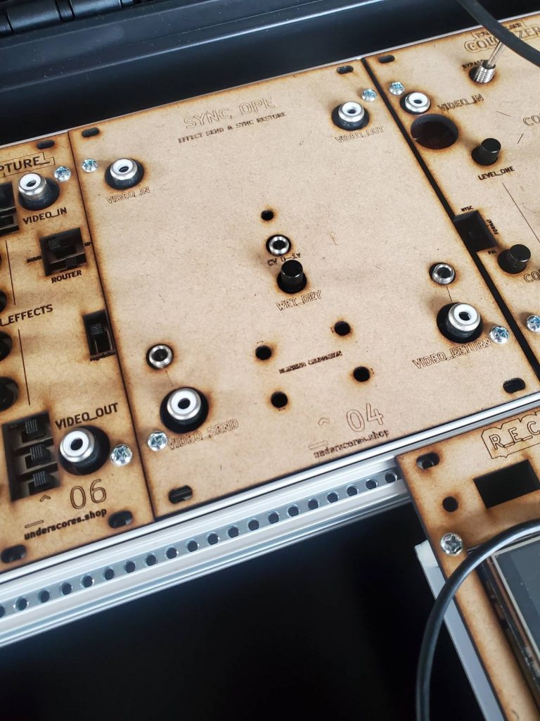
its fun to see them mounted together in a rack like this however this conversion is not the same as an actual eurorack module version of these circuits – which i do plan to design one day (closer to that day now that i finally have a euro-case built) the true eurorack versions will:
- use smd components and be designed to conserve hp
- have interface parts chosen to fit panels better rather than prioritizing what is cheapest
- layout of interface optimized for rack use
- have proper eurorack power headers
- hopefully expose some more of the controls with CV
my workflow for creating panels
this is shown with more detail in the video, but here is a written overview:
copy the pcb footprint into a new project and delete everthing except for the edgecuts, silkscreen and any footprints of interface parts
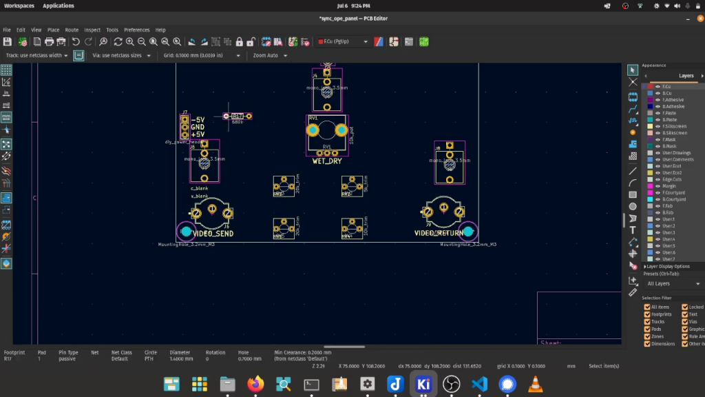
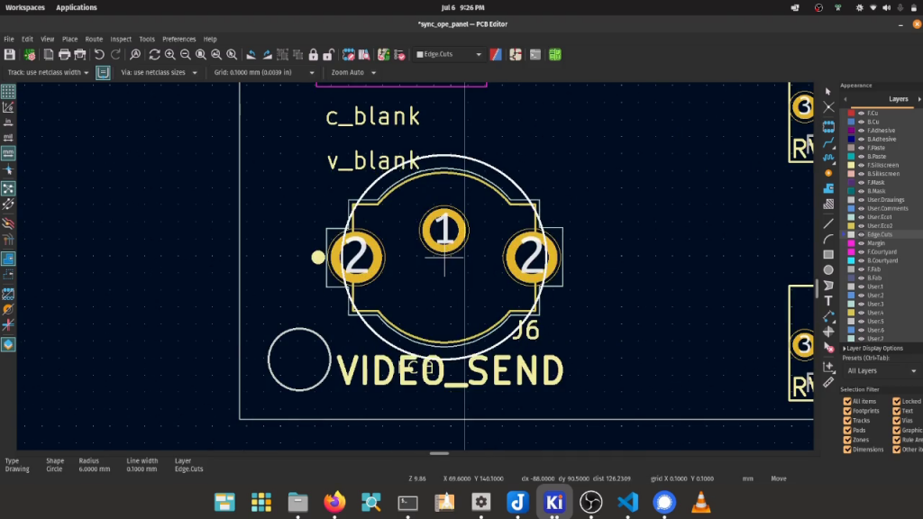
then replace each interface footprint with a edgecut hole to access it from the panel (based on a table of known hole sizes)
arrange the silkscreen however you want the panel to look – 3d viewer in kicad is useful!
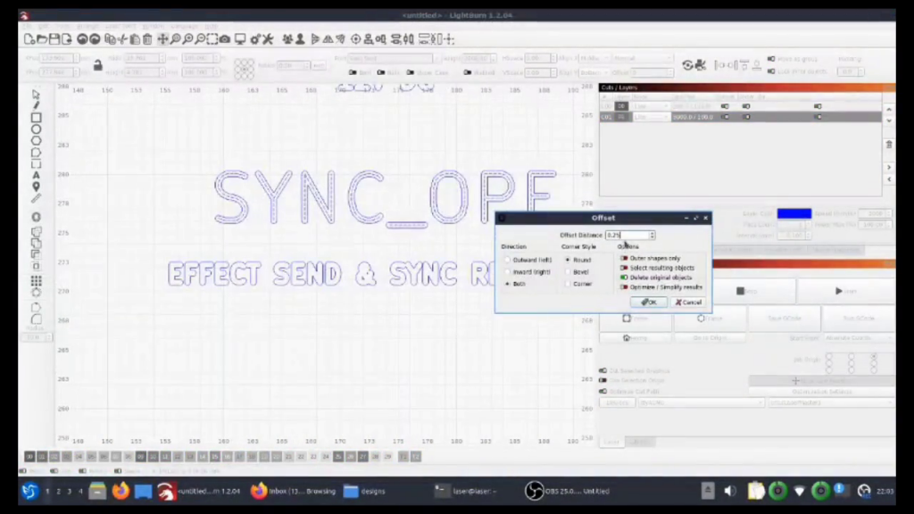
when you are happy with how the panel looks you can export it – use the usual GERBER export if you want to get it fab’d in FR-4. my method for getting designs into lightburn was to first export from kicad as SVG and then open these SVGs with inkscape and save a copy as DXF (it seems like lightburn didnt like some of the SVG format that kicad creates)
once in lightburn put the edgecut and silkscreen imports on different layers – you can add thickness to the silkscreen using the offset tool
then set your laser speeds, check the material is lined up with the cutting area and make the cut!