iv been selling diy video circuits in this shop now for almost 4 years, and designing and sharing software and hardware instruments before that for another 6 or so.
its been over a year since underscores released a new product though, as i have been working on a big idea that will (i hope) start a new phase for this project:
introducing:
TELEVOYANCE – an accessible sd eurorack video system

yeap, as i hinted in previous emails, underscores is going in on eurorack.
its no secret that the eurorack modular format is one of the most popular ways people are interacting with hardware audio instruments today – with lots of support for small/boutique creators, a strong resell market and plenty of online & offline communities.
its been a constant presence for me while designing and selling video instruments – lots of requests to support the format, (which i half addressed in the eurorack compatible enclosure kits available for some of my existing projects) but also a paradigm switch I have held some reservations about…
the parts i like the most about eurorack:
- its modular nature – both at a patch level and a module level, you are in charge of designing the instrument you play. which is something iv always been an advocate for.
- you only need to think about enclosures and power supplies once, per system, rather than every, single, time.. – then its just the fun stuff!
- its a popular format – whatever you think about the technicalities of the standard, its sometimes better for everyone to be on the same page (xkcd #927)
my main reservations have been:
- a steeper technical learning curve, compared to standalone instruments – less accessible to people not already “in the club”
- higher upfront costs, sharing enclosures and psus may save you money over time but acts as a barrier to getting started…
- the costs in general of building a eurorack system, and the culture of consuming more than creating with them…
my eurorack journey
this is why when i started designing for eurorack a few years ago it took a long time to get anything ready to release. I started thinking about how to make my modules more accessible to non-eurorack artists, while still appealing to those already with existing systems.
its quite common to see eurorack modules converted to standalone instruments with custom enclosures/power supplies, but looking at the economics of this i decided on the opposite approach:
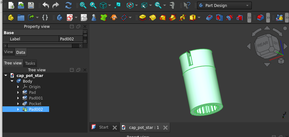
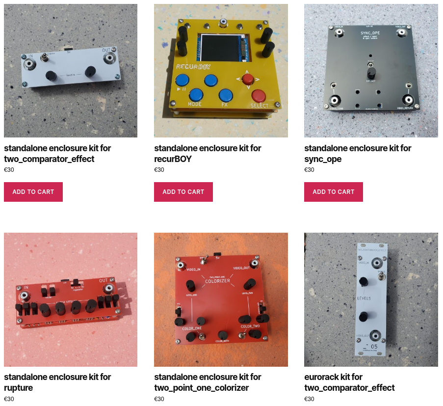
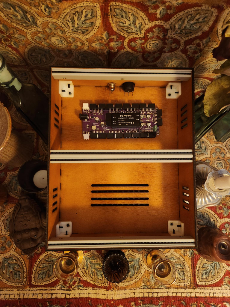
- I would design and offer, along side my eurorack modules, a series of low cost general enclosures & power supplies, aimed as an entry point for non-eurorack artists.. that can be used with my modular video synth and expanded / resold into the existing ecosystem.
the modular system
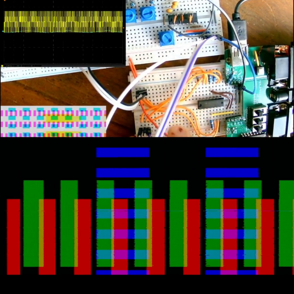
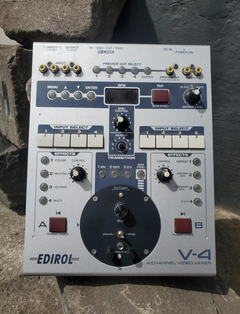
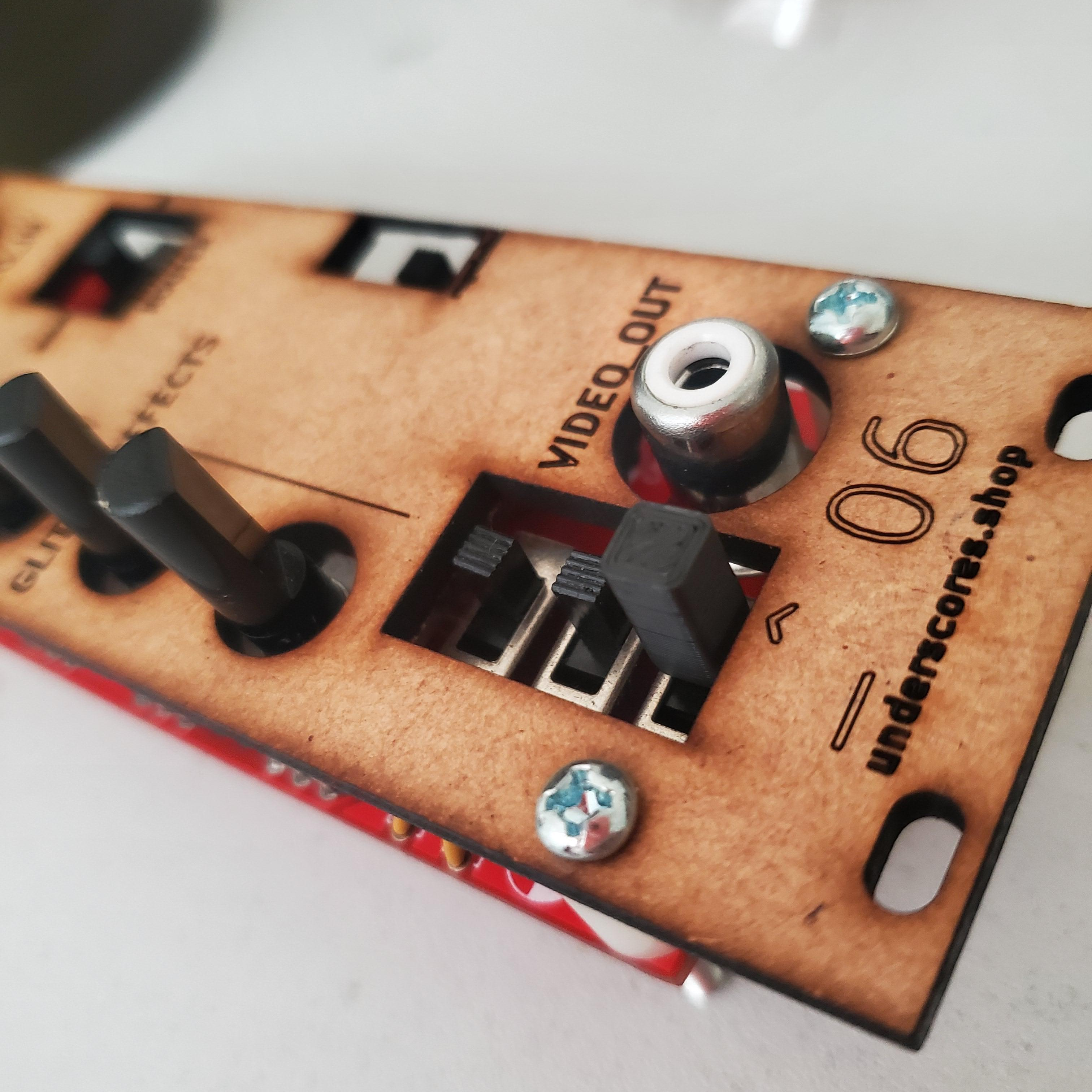
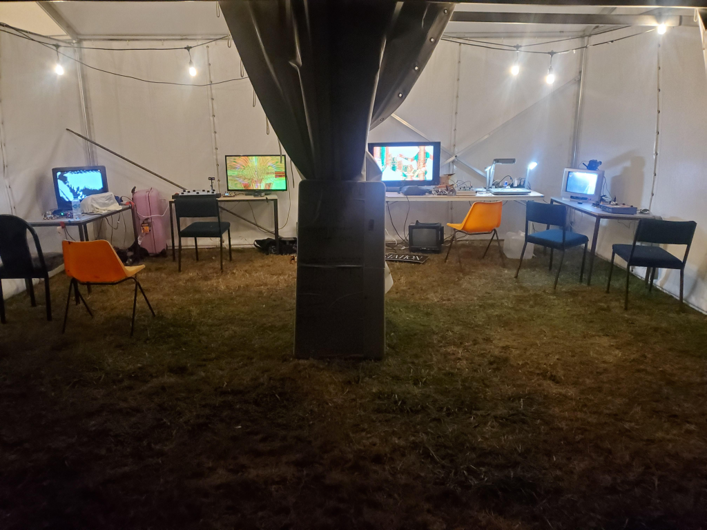
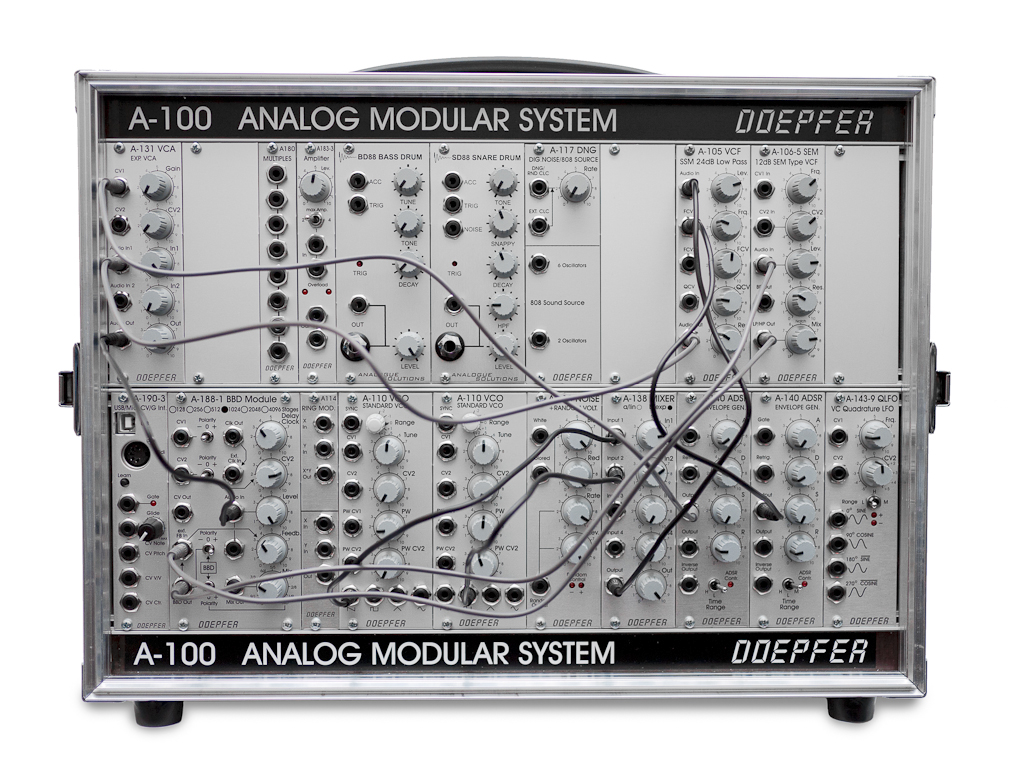
the video synth modules i have been working on are compatible with LZX RGB 1Vpp + sync over RCA. I am targeting SD analog video only, with a focus on composite video for the inputs and outputs.
Composite video is still a popular format for analog video artists, with its compatibility to old tvs, video mixers, glitch gear etc. both LZX and SYNTONIE (and im sure others too) are pushing the boundaries for professional HD analog (and digital) video modules, but i believe there is still room for an accessible sd system in this space.
i need your help
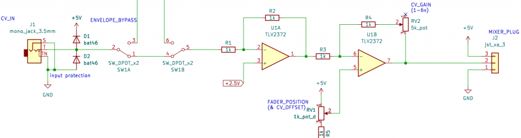
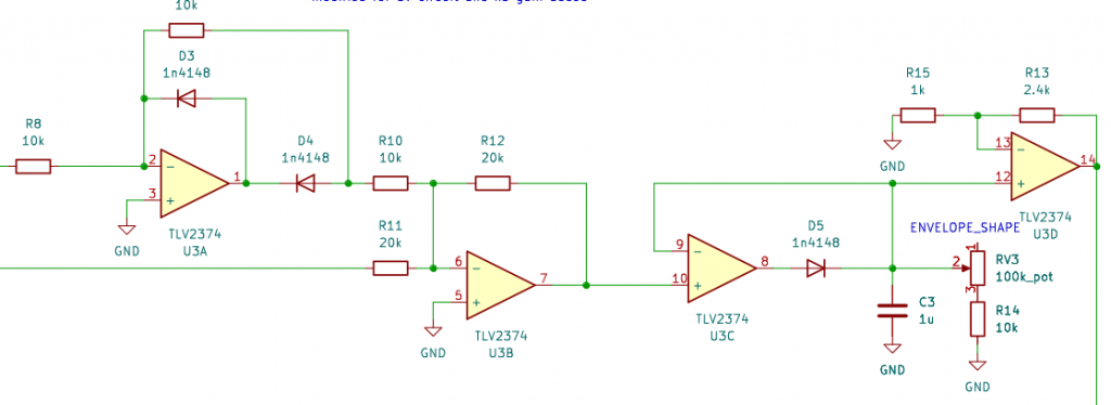
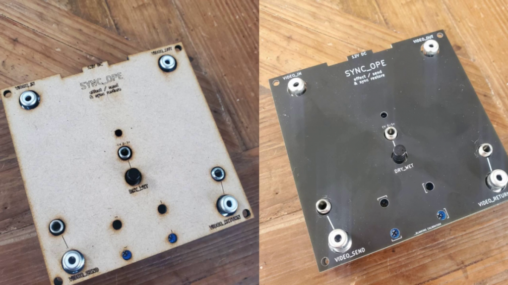
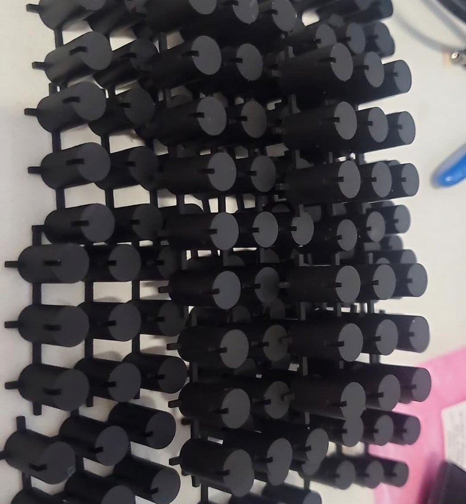
i have designed, funded, hand soldered and tested prototypes for a number of enclosures, power supplies and upcoming eurorack video modules in this system (modules include cvbs<->rgb encoders/decoders, processors, oscillators, comparators, shape generators and more)
I now need some help funding and testing this first production run (that needs to be ordered from pcb manufacturers in batches of atleast 10+). which brings me to the next announcement:
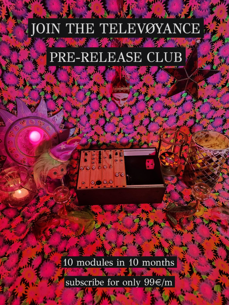
Join the TELEVOYANCE Pre-Release Club, a cooperative funded early-access subscription for new modules in the TELEVOYANCE video synthesis system:
Members receive first-edition modules before public release – a small-batch run at early supporter pricing, less than half the total retail cost and helping to fund and refine the final designs.
for the price of 99€/month you get ten assembled eurorack video modules over ten months. shipping is included with 2x modules send every 2x months
no prior eurorack gear or experience required – you will get everything you need to build the system included!
to me this idea seems like the ultimate win-win:
- I get the funds to manufacturer the final versions of the modules iv been working on and somewhere to send them once they are tested and working
- you get heavily reduced access to these modules ahead of release (and in a fun partwork building up of modular features over time…)
- plus the modules get some real world use and testing from a range of people in different contexts
- you get to provide feedback on them and help shape the final system (if you want to – no pressure!)
- we can all hang out and talk about video synths in the discord+matrix based chatroom
as you can imagine this offer is extremely limited (most likely to around 10-15 spots max) i really dont know how much interest there is likely to be, but its a pretty unique opportunity + a damn good deal! so if it sounds like fun to you go secure your spot here asap!