now that im back from summer festival work/holiday in Aotearoa i have been busy catching up on orders, arranging restocks and finishing up projects that were near complete end of last year.
restocks
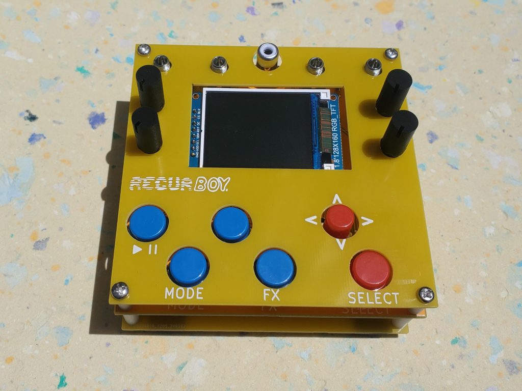
- there are a limited amount of recurBOYs in stock now with the parts for 10x more on their way
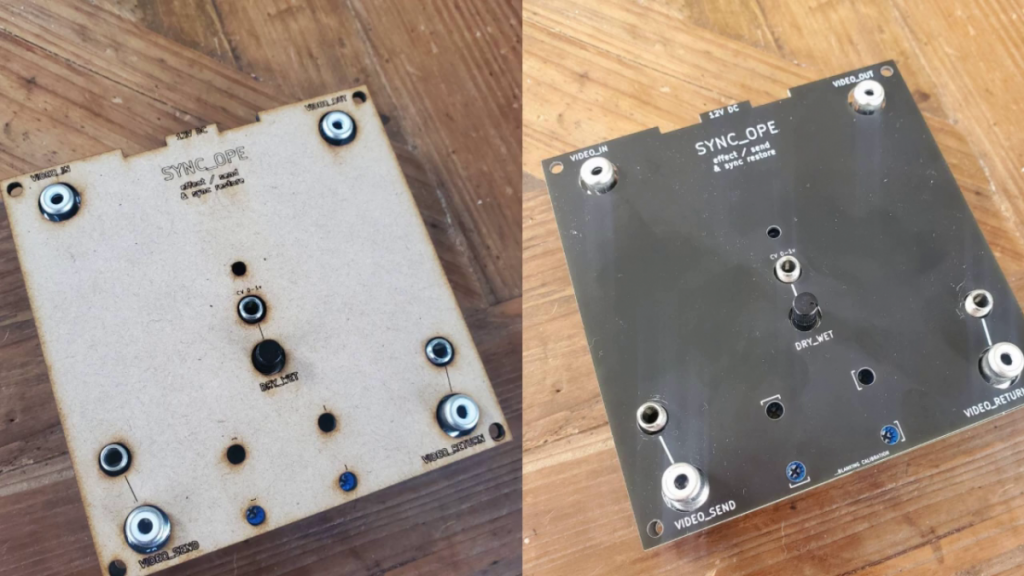
- sync_ope kits and assembled units are back in stock – possibly for the last time in this form since im planning a big redesign of these
limited enclosure kits in stock now!
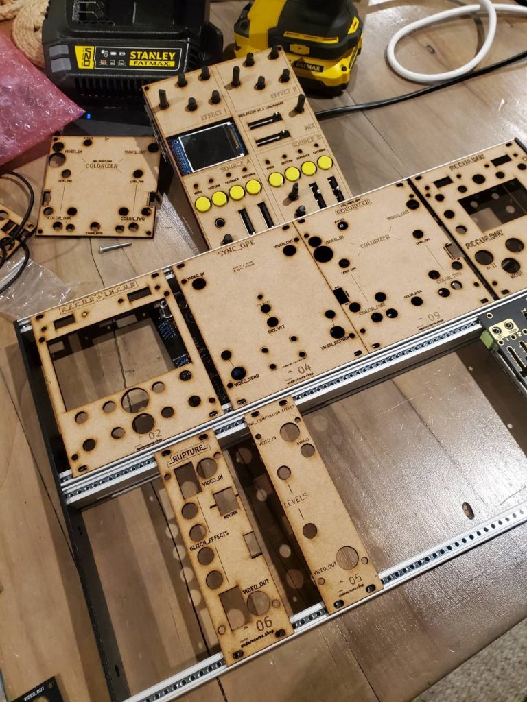
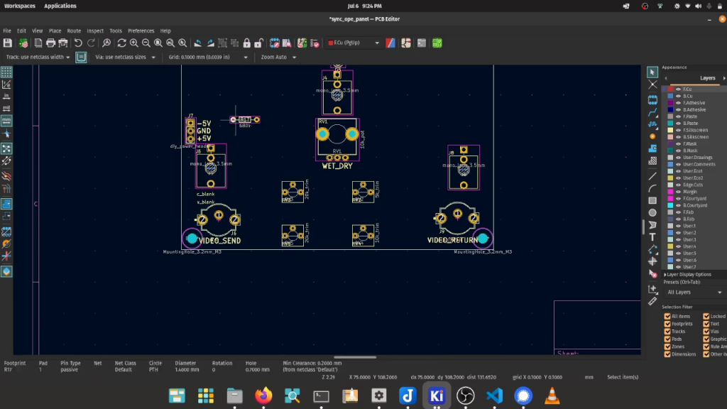
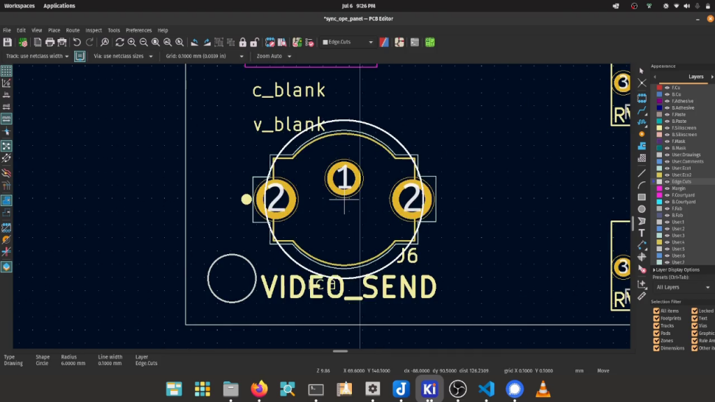
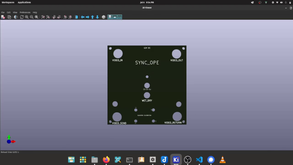
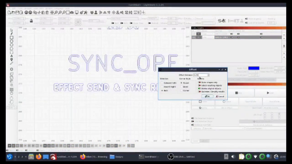
for years now people have been asking about enclosures for underscores circuits and i have be promising that they will be coming soon. around 18 months ago i dedicated a few weeks to prototyping my ideas on a lasercutter and wrote up/talked about the results. the idea was to design panels inside kicad, convert them to svg for lasercutting to prototype, and finally export as a gerber to get fabricated for production.
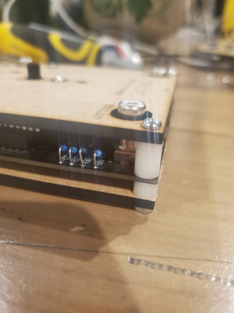
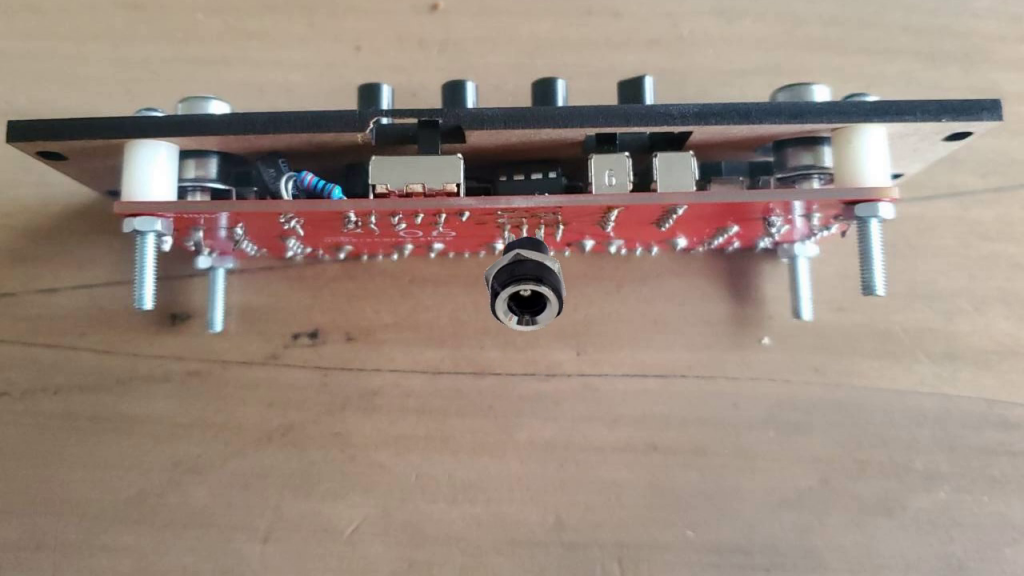
the main setback in releasing these enclosure designs as products was that when enclosed some interface parts such as potentiometers and slide switches were sitting too low to comfortably be used.
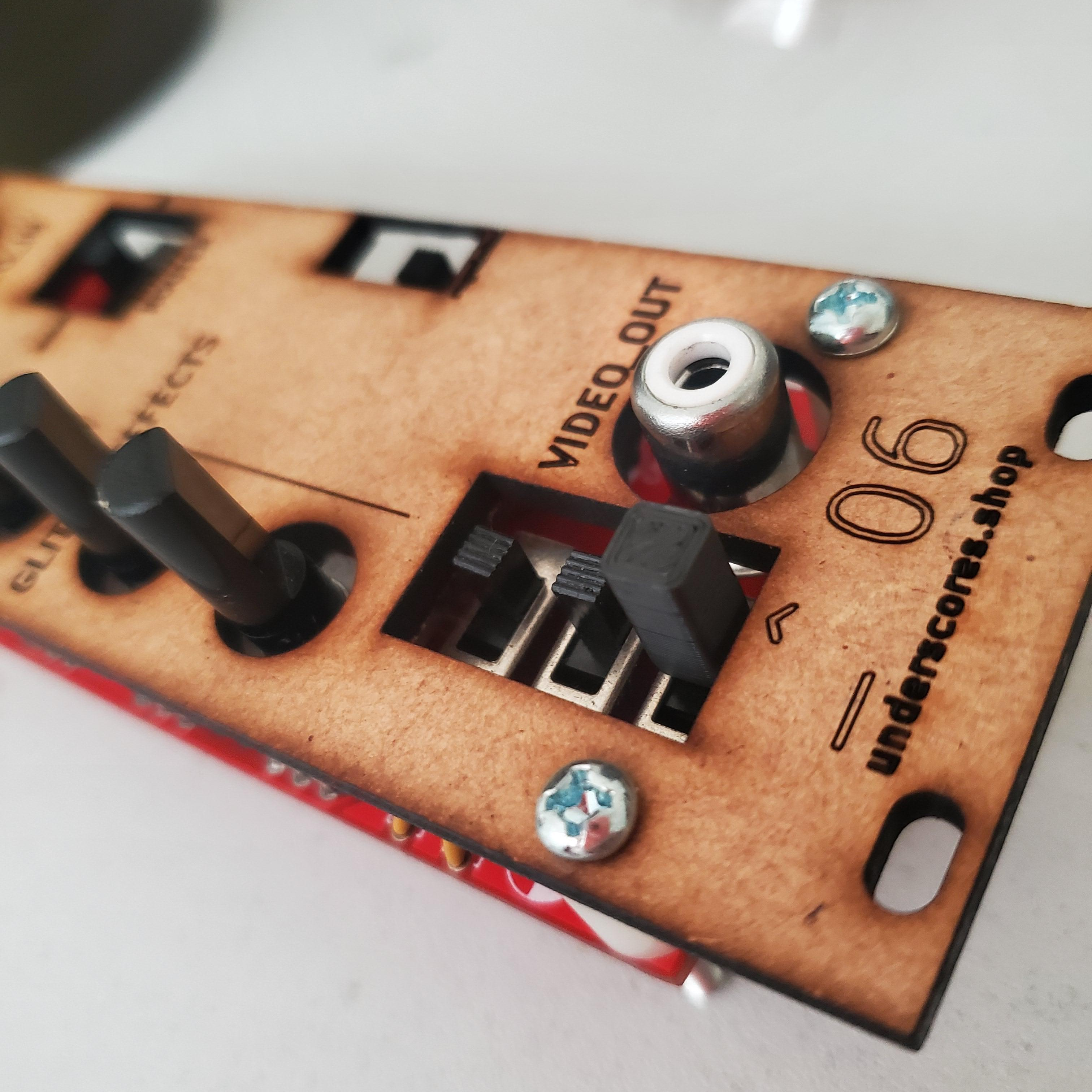
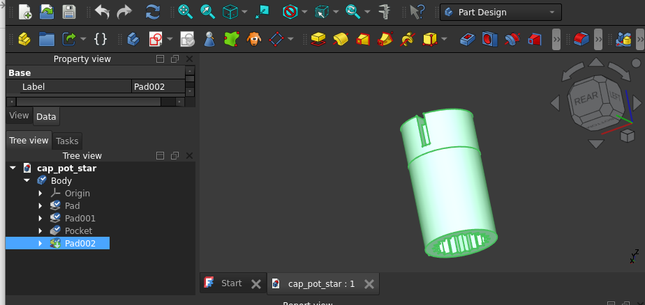
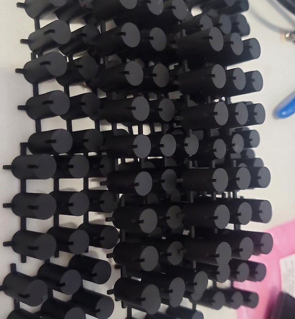
since i didn’t want to change the parts being used and couldn’t find suitable caps i decided to try 3d-model my own – this involved saving up for a 3d printer, learning how to 3d-model (with open source software only!), learning how to 3d print my prototypes, and learning how to get the final designs fabricated in small batches for resale.
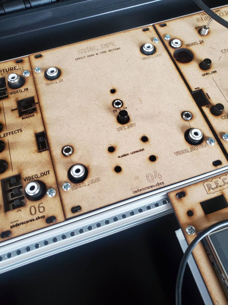
it has been a challenging but fun process and although there is a lot more to learn im finally ready to start stocking enclosure kits! i hope one day to write a longer blog post about this process with more technical details for those interested…
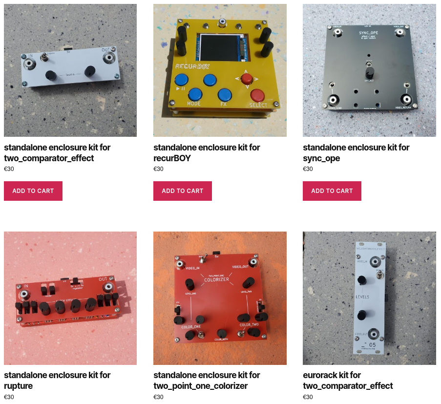
you can now find a category in the shop catalog page called enclosures where the following products are listed:
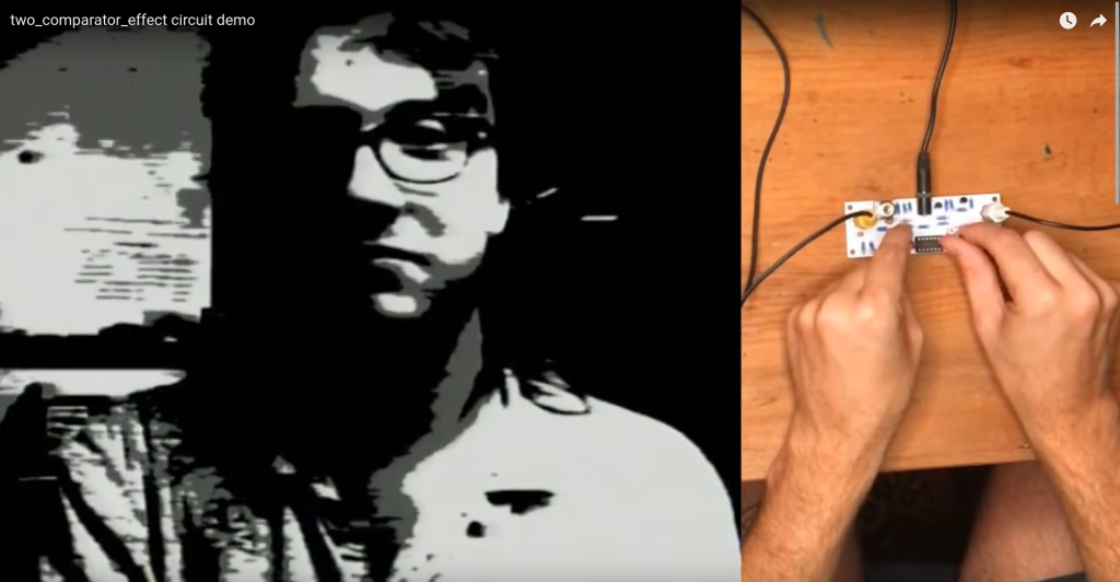
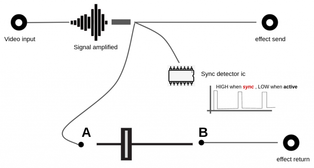
- standalone enclosure kit for two_comparator_effect
- standalone enclosure kit for recurBOY
- standalone enclosure kit for sync_ope
- standalone enclosure kit for rupture
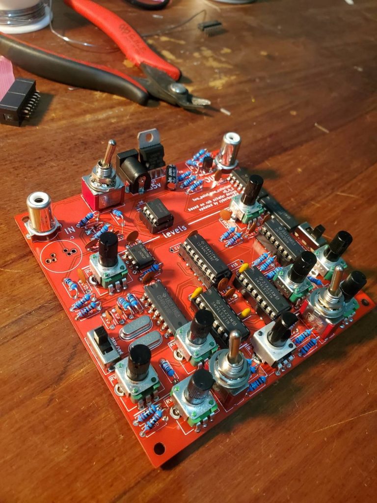
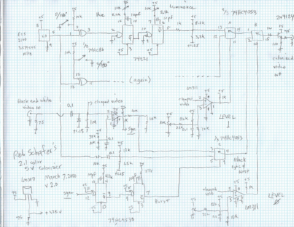
- standalone enclosure kit for two_point_one_colorizer
- eurorack kit for two_comparator_effect
- eurorack kit for recurBOY
- eurorack kit for _rupture_
- eurorack kit for two_point_one_colorizer
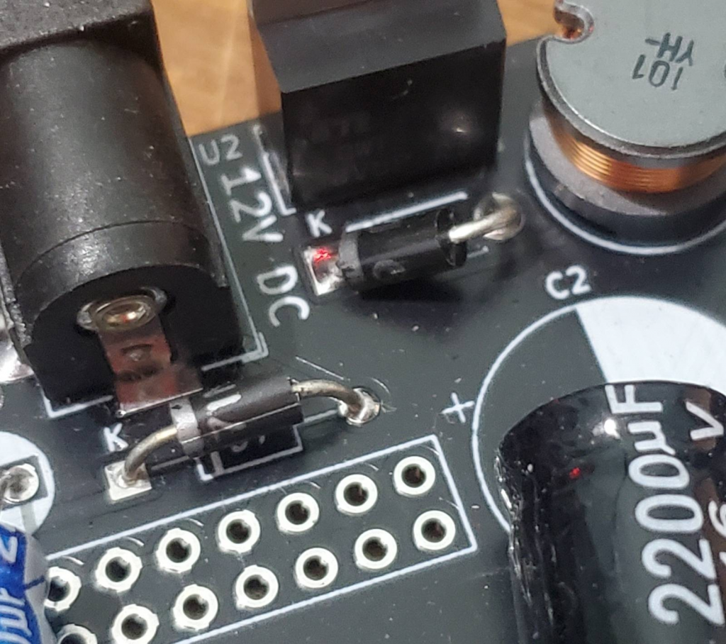
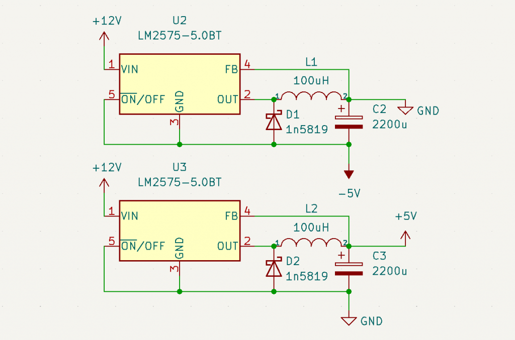
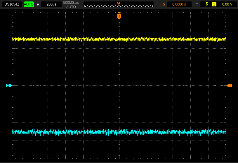
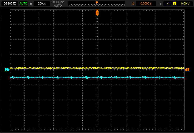
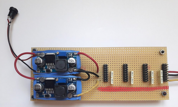
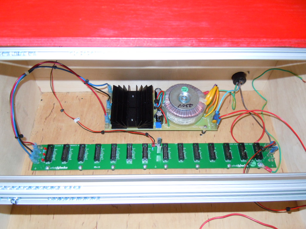
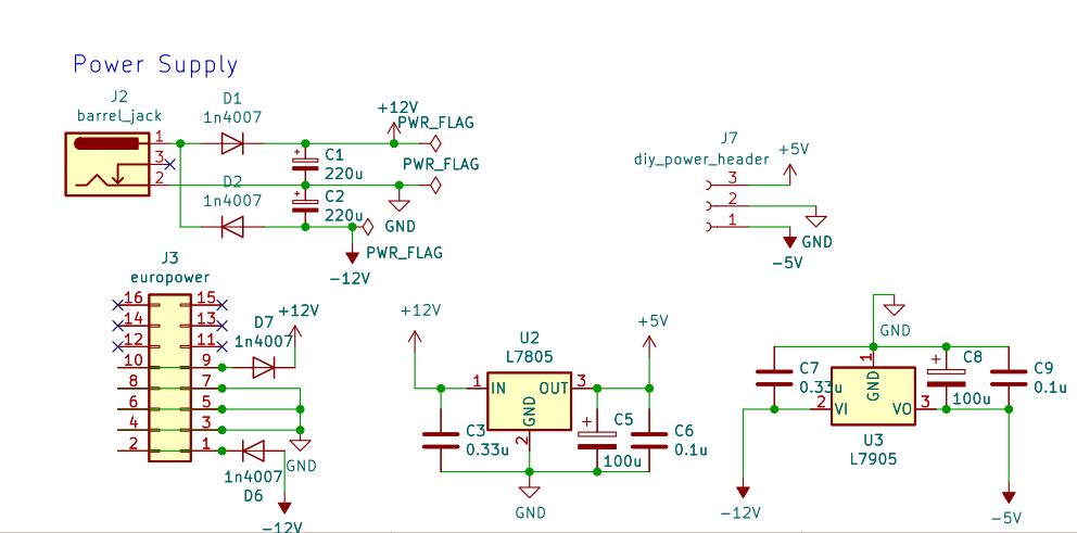
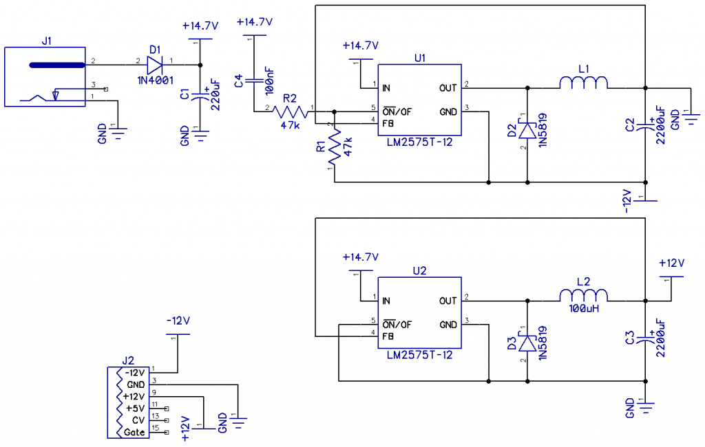
theres currently no sync_ope eurorack kit even though i have the panels for them – this is because of an issue thats been discovered with the power supply circuit requiring over 1A to correctly start the +/-5v rails – both my eurorack power supplies failed to provide enough power here and i don’t want to offer this until the issue is resolved – feel free to email me if you would like a sync_ope eurorack kit despite this disclaimer.
buying enough panels, caps, screws and standoffs to create kits for 10 new products all at once was challenging so currently there is only between 2-4 of each type of enclosure kit in stock. i have more parts coming soon so it shouldn’t be a long wait if you do miss out on your enclosures this round.