Categories
design

sync_ope psu revised

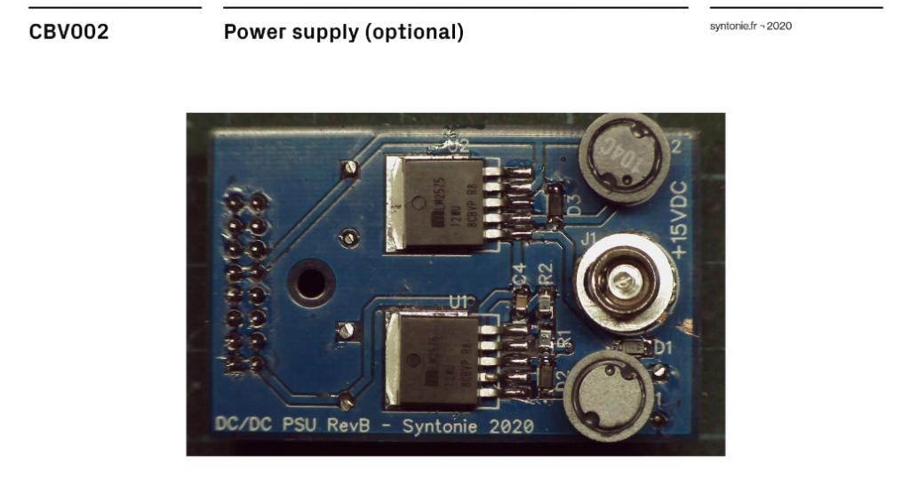
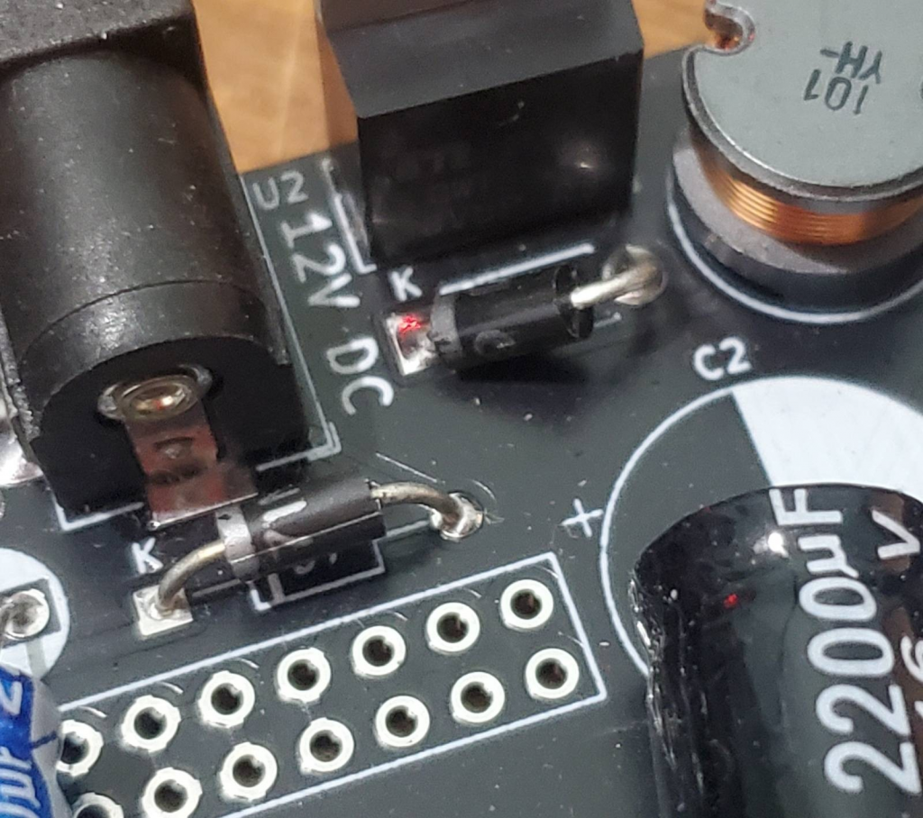
tl;dr – i updated the sync_ope psu design to only require single supply 12v dc to run – this version ( v1_0_0 ) is available in store now

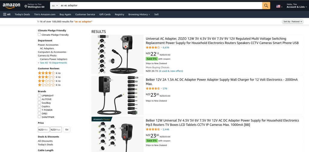
as discussed in this earlier post i decided it would be best to upgrade the sync_ope circuit to not require a difficult to source AC-AC adapter.

the schematic for new power stage

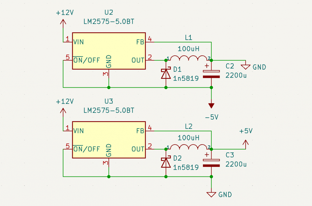
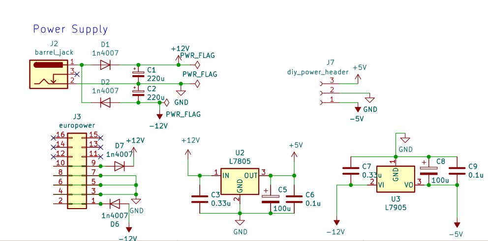
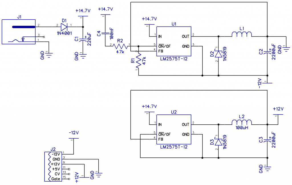
the new design uses two LM2575-5.0T step-down regulators, with one in inverting buck-boost configuration to generate the negative rail.

Part sourcing and testing

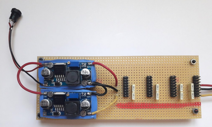
the rest of the newly required parts are easily and cheaply sourced from tayda – only the regulators themselves proved a bit more difficult:

I first tested the circuit using these Microchip LM2575-5.0WT s from mouser, which performed well while adding ~7euros to the BOM

next I explored a budget alternative – these (probably fake) National Semiconductors LM2575T-5.0 from aliexpress for about 1/10th of the price.

these two are not the same…

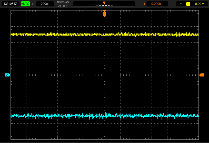
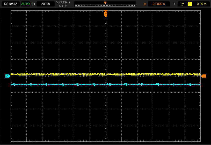
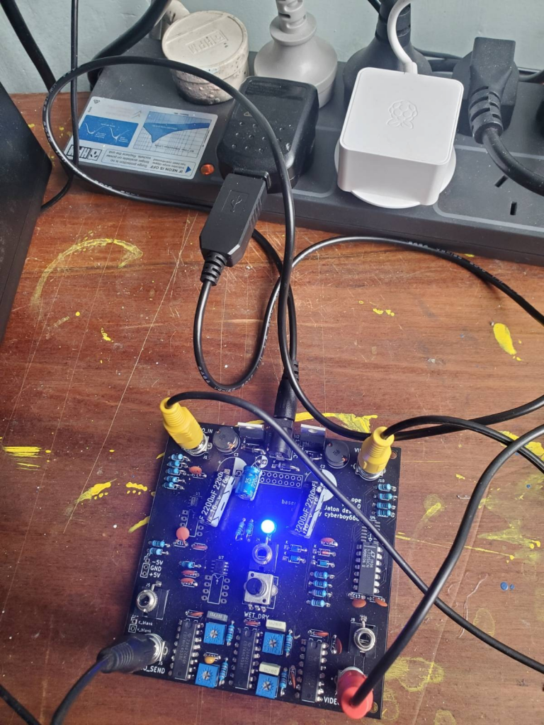
when powering the circuit from my 12v_1.5A supply both versions successfully generated +/-5v rails, however when i tried a cheaper 12v_0.5A supply only the more expensive regulators succeeded.

+/-5v rails as expected

the cheaper ones sat around 1v on one rail, and the other jumped to ~2v before falling back down to zero – while also quickly overheating enough to burn my (foolishly unsuspecting) fingers

not at all as expected (also HOT!)

this behavior is addressed in the TI_datasheet:

the start-up input current of the buck-boost converter is higher than
the standard buck-mode regulator, and this may overload an input power source with a current limit less than
1.5A. Using a delayed turn-on or an undervoltage lockout circuit (described in the NEGATIVE BOOST
REGULATOR section) would allow the input voltage to rise to a high enough level before the switcher would be
allowed to turn on.

however my various attempts to use delayed turn-ons / larger input capacitors failed to correctly bootstrap the circuit with these regulators.

i found online a description of a problematic similar sounding method to generate +/-12v rails for eurorack that seems to use fake buck-boost regulators. Im not sure if this is in any way related, but still.

a nozoid eurorack supply using aliexpress regulators in inverting buck-boost configuration

im always game to try out cheaper parts from questionable sources – in many cases they can be just as good for a fraction of the price. but in this particular case, given:

  • that in general you shouldnt cut corners on power-supplies
  • it failed for me in a way that could hurt people
  • there is reports of related issues using similar parts online

Im happy to stick with the more expensive mouser sourced regulators !!

plus now i can run my sync_ope from a single 5v_usb with this cheap boost supply (i know – iv learnt nothing !)

version control

this is the first major revision I have done to an underscores circuit that is in production. it is a good opportunity to think about the process as I want all these projects to be living / always improving.

I created a branch in git for this release and committed all the changes over the last few months to this feature branch – this ensures the changes and revisions are available yet also preventing people downloading WIP gerbers from the main page.

when everything is tested and ready to go i can then merge this feature branch into main.

on release i also need to update the project in a few other places:

  • the shop description
  • the circuit booklet
  • the circuit images (in this case decided not to bother with these)
  • the video walkthroughs – videos.scanlines is fine but youtube will not allow for editing existing videos so i either need to re-upload a new one or find a way to amend the existing one

Categories
design

sync_ope psu reverie

tl;dr – im thinking of making a revision of sync_ope to replace the ac-ac psu input with a standard switching ac-dc one

UPDATE: this has been implemented in v1_0_0 – read more about it here

sync_ope is a project iv been collaborating with Gael Jaton on for a few years. initially a concept dreamed up and tested on bread-board, iv worked on a fair few design iterations based on feedback and support from the wider community – we presented a prototype of the concept at FUBAR_2020, and continued improving it via discussions on the scanlines forum.

a over-simplification of her beauty

its been quite slow progress – and like many diy / community driven initiatives (who get passed around and only prioritized in short bursts & on productive weekends) has some built-in identity insecurities:

  • sync_ope is designed to be diy & beginner friendly – spaced out across all of a 100x100mm pcb- with footprints for even the specific video-ic’s in DIP packaging
  • the use case however requires already owning analog-glitch devices, and having pre-established capture flows where sync dropouts are a problem
  • the circuit is strictly analog, and more complicated/advance than many of the other ‘entry level’ underscores projects iv been prioritizing – one LT1251 ic can cost more than a single-board-computer!

Many similar projects in this realm would have fully committed to serving (only) the eurorack video synthesis community – where there’s an active base of designers and users creating complex functions with analog circuitry:

the advantage of this is you don’t need to (re)design common function blocks like power supplies and enclosures – there is even many design best-practices to follow to ensure compatibility

an (ac-ac) eurorack power-supply and case

the problem i see with this approach is that it can be off-putting for some people who havnt fully invested in the modular setup – where certain design preferences and restrains do not apply to them. by only serving the established (and well-enough off) we risk alienating those on the fringe.

the beauty of the sync_ope circuit is it can be just as interesting and useful in a mess-of-circuit-bent-mixers&diy-guitar-pedals as in a large modular synth system

the muddle

technically, the circuit requires a dual power supply to operate (unlike some of my other projects which can be run from a single usb-supply)

this is common and expected in euro-rack-land where all systems carry +/-12v rails. however it is less common for the average ‘non-modular’ hardware setup…

sync_ope’s power supply schematic

the current design has both a eurorack header – that takes +-12v straight from the rails – and a 12-15 AC barrel-jack input – that uses a Rectifier Diode Bridge to convert alternating current to dual dc.

i thought that this implementation struck a balance between serving those who may want to rack-mount it (atleast, all the interface controls are front facing!) and those who will just wanna plug it into a wall.

however as i prepare to distribute a small number of these circuits internationally im discovering that AC-AC wall-warts can be quite tricky to come by.

a search for ac-ac adapter returning a page of AMAZONS-CHOICE for dc ones doh

a different approach that i have been seeing recently is to start with a single dc supply and use a step-down regulator in inverting buck-boost configuration to generate the negative rail.

since composite video sits around the 1-2v range +-5v is plenty of headroom for this circuit to operate. we could start from any single dc 12v wallwart (or the positive side of a eurorack-powerrail) and create the dual 5v’s we need onboard.

lzx are powering their new 3rd gen modules with 12v single supplies and syntonie has optional dc_psu_boards for their cbv* line

syntonie’s stand-alone to euro-module adapter board

although the (ac-ac) current version of sync_ope is available in store now im already thinking about making another revision to the board to use single dc supply instead.

it could follow a similar configuration to Bastiens psu schematic below – instead using LM2575T-5.0 to create the +-5v rails we want. this change may increase the total BOM cost slightly – but since its already quite an expensive circuit i also think its worth ‘doing it right’

syntonie’s CBV002_PSU_Schematic.png

i can already imagine another future revision with smd parts and a more compact ‘rack first’ interface design that would better suit the modular crowd. but for now i will continue to try bridge the gap between this and a more hacky diy approach.

if you understand the ac-ac psu problem im describing and want a sync_ope now anyway then this version is for sale right now in the shop! but if you think you would rather wait some more months and hold out for an ac-dc supplied version then this is also an option for you too !

the beauty of open source is multiple forks of a project can co-exist. time will tell whether this revision will be a direct successor of what we have now or an alternative version