im happy to announce the launch of a new product for underscores : the tv_wall_mapper – an open-source cross-platform application for creating synchronized tv wall installations
although many underscores projects have software components to them this is the first purely software application we have released – its also the first of a series of open-source tools for video installation work that i have been working on inspired by my own art practice over the last year.
project overview
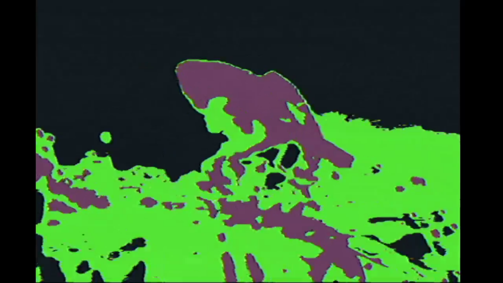
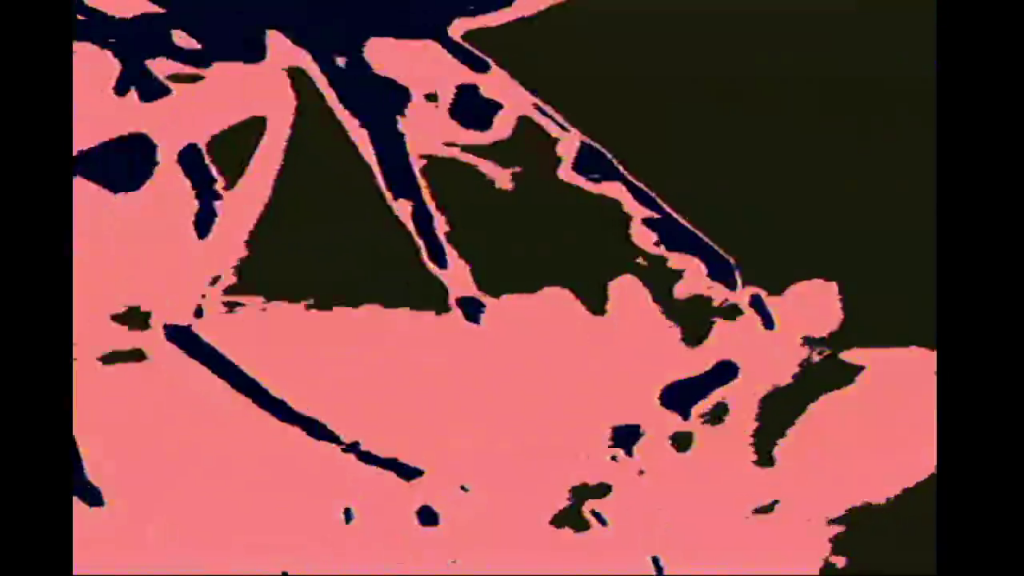
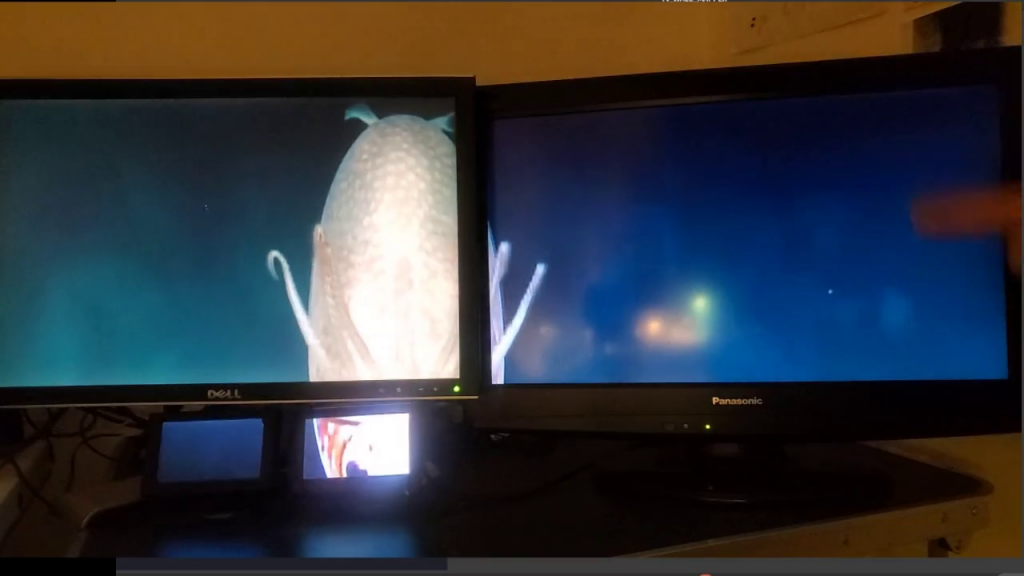
tv_wall_mapper is a software designed to help you create a synchronized tv wall effect – where many tvs are installed together to output different portions of a single cohesive video feed.
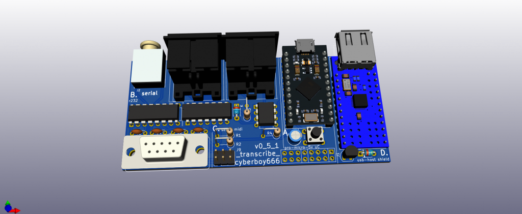
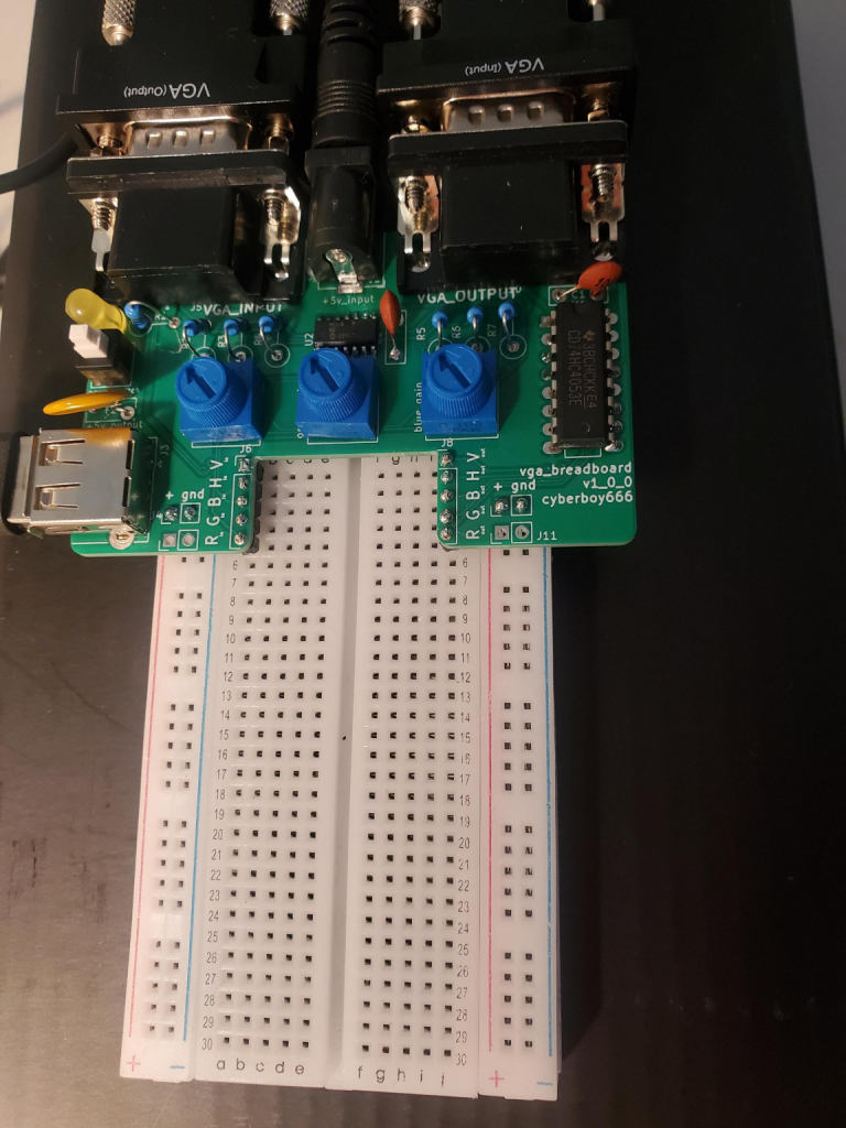
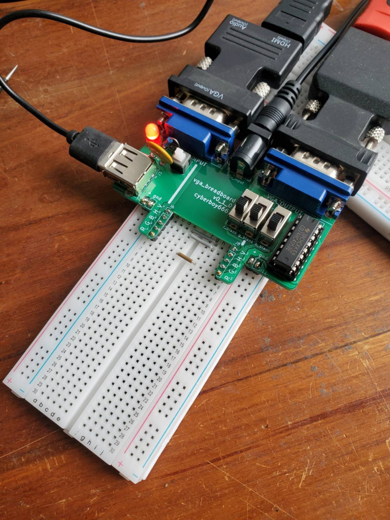
there are a few different hardware options (outlined in the project readme) that this app can work with to achieve this effect – perhaps the best being the use of off-the-shelf tv_wall_controllers such as these:
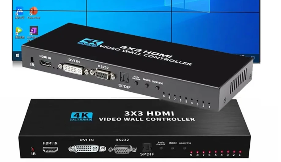
these kinds of controllers are designed for commercial spaces where multiple (expensive) bezelless tvs are used – however by using this software we can define a mapping so that any physical arrangement of tv’s can be used:
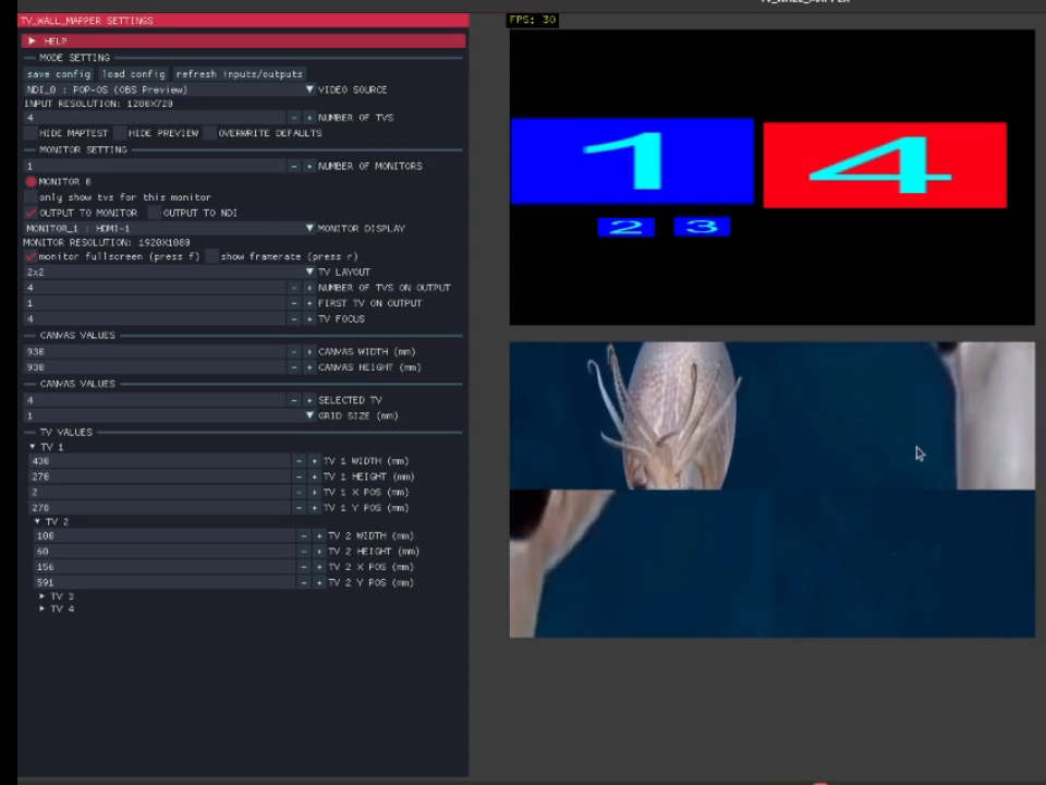
i made a tutorial video where i walk through the hardware/software options and show how to set up and map this demo tv wall:
inspiration and motivation
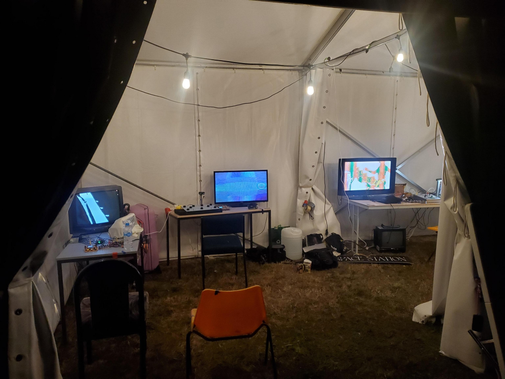
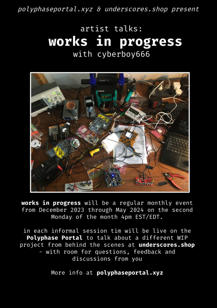
this project was inspired by a recycled tv wall installation we built for the dojo stage at Twisted Frequency Festival 23/24 – you can hear a bit more about this project in my WORKS IN PROGRESS 02 artist talk:
under the hood the video mapping is done using openframeworks + some glsl shaders (both things i had some experience writing for other projects)
it is possible to achieve this effect with existing projection mapping software – for our installation originally we were using resolume with the hardware controller to achieve this.
the main reason i have taken the time to polish and publish this little diy alternative:
- i use pop_os as my daily driver and wanted an app that could run on this (which resolume does not)
- resolume is proprietary and expensive – it is important to have open and accessible alternative tools for artists
- building on the unix philosophy of creating software tools that are designed to do one thing well – this app aims to be simple and lightweight (you can always “pipe” video from other apps using NDI )
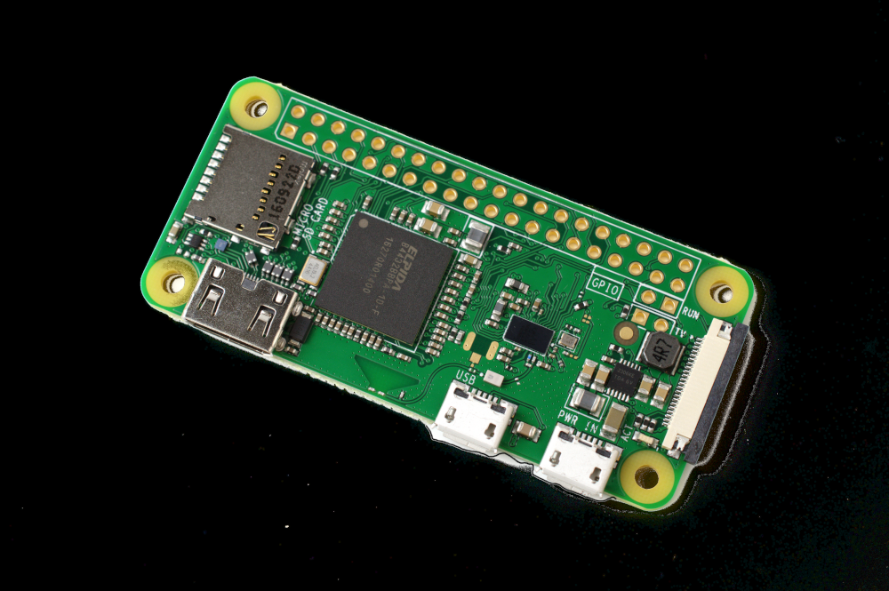
- a nice side-effect of having a light-weight cross-compatible app is we can also run it on single board computers such as raspberry pi’s – commonly used for installation work
compared with hardware releases which are relatively easy to price (taking into account the cost of parts, labor, creative work and similar products on market ) it is harder to know how to price software -especially “small specific task” apps such as these. the code is open source and available via the github for anyone to compile for free. i have decided to also offer pre-compiled versions of these apps via the underscores shop for a small donation (a sliding scale between $10-100) hopefully this strikes a balance between making it accessible to those without the funds and also sustainable to invest our time into.
this kind of release is new for us and im very happy to hear any thoughts or feedback from those reading about it here